Annex I
BOUNDARIES OF SUB-DIVISIONS OF THE CONVENTION
AREA
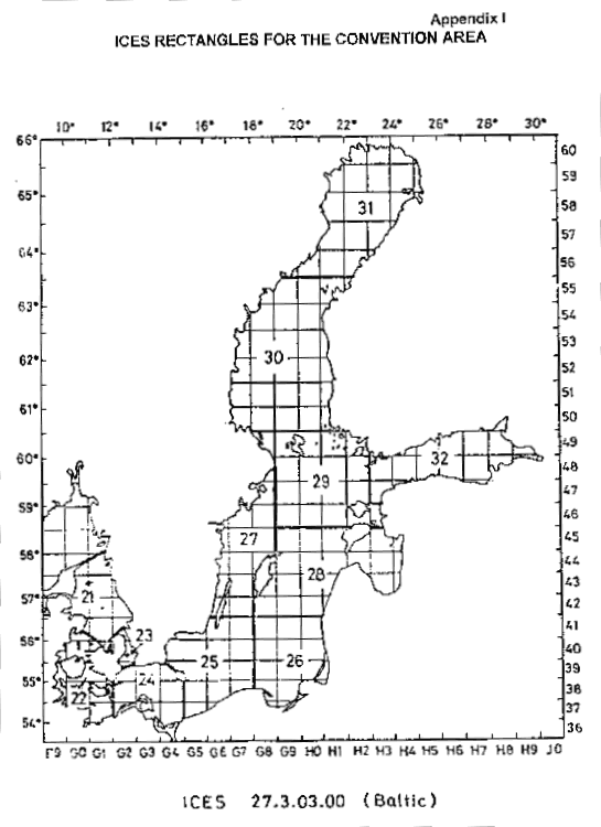
The Sub-divisions of the Baltic Sea and the Belts are given on the map (Appendix I) and the boundaries at sea are described below:
Sub-division 22
Sub-division 23
Sub-division 24
The western boundaries coincide with the eastern boundary of Sub-division 22 and the southern boundary of Sub-division 23. The eastern boundary runs along the line from Sandhammeren Light to Hammerode Light and south of Bornholm further along 15o E.
Sub-division 25
Subdision 30
Sub-division 32
Appendix I

Annex II
Explanatory diagrams to Fishery Rule 9.4
Re.: FIGURE I
It shall be permitted to attach to the outside of the lower half of the codend of any trawl or of a similar net, any canvas, netting or other material (C) for the purpose of preventing or reducing wear.
Such material shall be attached along the forward
(A) and lateral (B) edges of the codend only.

Re.: FIGURE 2
It shall be permitted to attach to the outside of the codend and the lengthening piece a strengthening bag (D).
The strengthening bag is a cylindrical piece
of netting completely surrounding the codend and the lengthening
piece (covering the upper and lower half of the codend and the
lengthening piece).

Re.: FIGURE 3
The mesh opening of the strengthening bag (2 a sb)shall be at least twice as large as the mesh opening of the codend (2 a cod): 2 a sb = 2 x 2 a cod (E)except that its minimum mesh opening shall not be less than 80 mm: 2 a sb 80 mm.
The strengthening bag may be attached at the following points:
a) at its forward edge (F), and
b) at its rear edge (G), and either
c) laced circumferentially to the codend and the lengthening piece around one row of meshes (H), or
d) laced longitudinally along a single row
of meshes (J)

Explanatory diagram to Fishery Rule 9.5
FIGURE 4
It shall be permitted to use in trawls (and in similar nets) a nonreturn net or flapper.
The flapper may be attached in front of the codend (K) or inside the codend (M). The distance from the point of forward attachment of the flapper (K;M) to the rear end (N) of the codend (L) shall be at least three times the length of the flapper (Lfl): L 3 x Lfl
The mesh opening of the flapper (2 a fl)may
be smaller than that of the codend (2 a cod):
2 afl
< 2 a cod.

Annex III
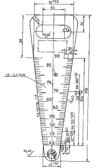
Instructions for manufacturing (mesh gauge =A=)
1. Tolerance for the width of the gauge in the effective range
40-90:+0.2 mm.
2. The marking begins at the gauge pin for 40. The appropriate width of the measure sheet 40+0.2 is to be found rectangular to the midline on the mesh gauge with a slide gauge.
3. Inscription, dimension figures gauge pins engraved 0.1 or engraved 0.5 (punching tool respectively scriber).
4. All edges broken and smoothed.
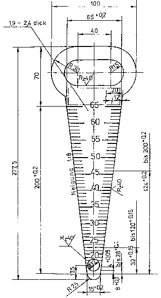
Instructions for manufacturing (mesh gauge =B=)
1. Tolerance for the width of the gauge in the effective range
15-65:+0.2 mm.
2. The marking begins at the gauge pin for 15. The appropriate width of the measure sheet 15 + 0.2 is to be found rectangular to the midline on the mesh gauge with a slide gauge.
3. Inscription, dimension figures gauge pins engraved 0.1 or engraved 0.5 (punching tool respectively scriber).
4. All edges broken and smoothed.
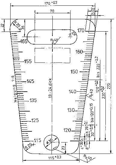
Instructions for manufacturing (mesh gauge =C=)
1. Tolerance for the width of the gauge in the effective range
80-130:+0.3 mm.
2. The marking begins at the gauge pin for 80. The appropriate width of the measure sheet 80 + 0.3 is to be found rectangular to the midline on the mesh gauge with a slide gauge.
3. Inscription, dimension figures gauge pins engraved 0.1 or engraved 0.5 (punching tool respectively scriber).
4. All edges broken and smoothed.
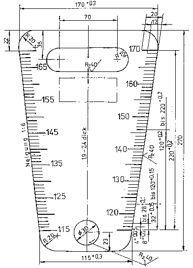
Instructions for manufacturing (mesh gauge =D=)
1. Tolerance for the width of the gauge in the effective range
115-170:+0.3 mm.
2. The marking begins at the gauge pin for 115. The appropriate width of the measure sheet 115 + 0.3 is to be found rectangular to the midline on the mesh gauge with a slide gauge.
3. Inscription, dimension figures gauge pins engraved 0.1 or engraved 0.5 (punching tool respectively scriber).
4. All edges broken and smoothed.
Annex IV
Exit Window (Model 1)
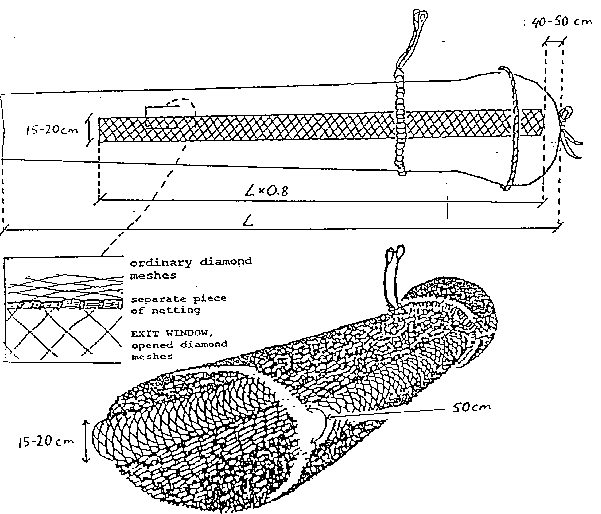
Two exit windows with plastic coated, fully opened diamond meshes shall be attached to the codend of trawls and danish seines in the cod fishery. The mesh opening shall be no less than 105 mm. The exit windows shall be attached with a separate piece of netting (between the ordinary diamond meshes and the meshes of the exit window). The mesh size of the separate netting shall be identical to the bar length of the exit window netting times the square root of 2.
The exit window shall be attached on both sides
of the codend and the distance between the rear end of the codend
and the window shall be 40-50 cm. The length of the window shall
be 80 % of the total length of the codend and the height of the
window shall be 50 cm. The window shall be mounted in a way that
gives an opening between the upper and lower seams of the window
of 15-20 cm. Exit Windows (Model 2)
Specification of 105 mm square mesh window in a 105 mm codend
Identification of the windows
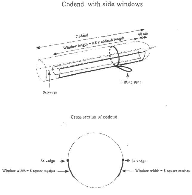
The windows shall be rectangular sections of netting in the codend. There shall be two windows in the codend.
Size of the windows
Each window shall have a minimum width of 45 cm along its entire length. Each window shall have a minimum length of 3.5 m measured along its sides and the length of the windows must not be less than 80% of the total length of the codend.
The netting of the windows
The meshes in the windows shall have a minimum mesh opening of 105 mm.
The meshes shall be square meshes, i.e. all four sides of the window netting will be cut all bars . The netting shall be mounted such that the bars run parallel and perpendicular to the length of the codend.
The window width shall be 8 open square meshes.
Location of the windows
The codend shall be divided into upper and lower panels by selvedges running down the port and starboard sides .
The two windows shall be located in the lower panel, immediately adjacent to and below the selvedges .
The windows shall terminate 40-50 cm from the codline.
The forward end of the window shall be joined to 8 meshes width of the normal codend netting . One side shall join to the selvedge or be joined immediately adjacent to the selvedge and the other side shall be joined to the normal codend lower panel netting following a straight all knots cut .
Mesh opening in the whole codend
All parts of the codend shall conform to a minimum mesh opening of 105 mm.
|
IBSFC 20, Hozastr. 00-528 Warsaw POLAND Phone: (48-22) 628.86.47. Fax: (48-22) 625.33.72. E-mail: [email protected] |
Broken links, suggestions? Webmaster Marc Vanbrabant (Jr.) Dampoortstraat 23 8310 Brugge BELGIUM Phone: (32-50) 35.37.67. E-mail: [email protected] |